AME Collection
Designs

AME Fan Motor With Driver
AME Axial Flux Motor and Three Phase Full Wave Fan Motor Driver merged in one structure. Componants: ROHM BD67173NUX-E2 TAIYO YUDEN JMK107BB7475KA-T SMD Resistor 10kOhm Pin strip header with 2,54mm ...

AME Jewelry Earring Artwork
Isn't it nice to be able to do brandnew technical stuff on one hand - on the other hand the full design freedom gives you some artwork tool. This is a design study of an earring 3D full silver ...


AME Bandpass-Filter - Design And Realization
This article will provide some deep dive into the figured out goal: To realize an optimized full 3D-printed AME-filter by simulation without additional manual tuning effords

Plug And Play Adapter To Use BD67173NUX Chip On Arduino Breadboard
Adapter to plug BD67173NUX in an Arduino-Breadboard. This Adapter was used to test different circuit examples to drive our Axial Flux Motor and merge the driver and the motor in one ...

Socket-Adapter For ATmega8 TQFP32
Socket-Adapter for ATmega8 TQFP32 to program, flash and test the chip. This Adapter was designed to simplify the programming of the ATmega8 Chip before populating the brushless motor controller.

3D-AME Antenna Matrix
The article describes how tiny three-dimensional antenna components are being incorporated into a panel designed for radiation matrix, tailored for use in phased array antennas.

AME Antenna Array
Explore innovative 3D flat formfactor technology by AME, improving radio frequency efficiency. Learn how this innovative method changes antenna applications for better miniaturization, simpler ...

J.A.M.E.S Coin NFC Business Card
Advancing the J.A.M.E.S Coin Design into the shape of a Business Card to easily provide your contact information data without using paper. Using our provided design, you can create one by yourself.

J.A.M.E.S Coin NFC On AME - PrintC
The purpose of this educational design is to show how to replace external COTS capacitors with AME capacitors that can be embedded into the final AME structures. To highlight the procedure with a ...

Brushless Motor Controller – 3D Wires
Based on the brushless motor controller – PCB design, published by the J.A.M.E.S Team, this new design implements some three-dimensional wire-aspects. In the previous PCB design, it was necessary ...

AME Chip Heatsink Capacitor
This design can be used for hardware IT-security issues, to protect a semiconductor chip against espionage, and reverse engineering by opening a chip housing.AME can provide bare chips with ...

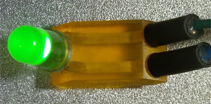
J.A.M.E.S Coin NFC Side Mounted LED
This design is intended to bring two additional aspects to the NFC story. Side mount and integration of components are intended to spice up to the NFC story. The design contains two print jobs, the ...

Brushless Motor Controller - PCB
The brushless motor controller is designed to be suitable to control the triangle coil motor design, published by the J.A.M.E.S Team. At the current stage, it is a traditional PCB design which can be ...

AME 3D Test Coupon Testcase 1.0 PTC
J.A.M.E.S is providing this AME 3D Test Coupon to verify the reproducibility of three-dimensional wiring designs in a harmonized formfactor over the complete printing area. The TestCoupon is designed ...

J.A.M.E.S Coin NFC On AME 2D To 3D
The goal of this design is purely educational. It is intended to provide hands-on approach on how to combine elements of traditional eCAD design tools with three-dimensional mCAD tools. The benefit ...

AME 3D Test Coupon Testcase 2.0
J.A.M.E.S is providing the second AME 3D Test Coupon to verify reproducibility of specific three-dimensional AME design elements. While this Test Coupon was originally designed for the DragonFly IV ...

J.A.M.E.S Coin NFC Flat Panel
This design of a J.A.M.E.S Coin is provided to combine full 3D-wiring aspects and NFC functionality to an automatic level of component implementation by Pick and Place. 10 Coin structures are ...

J.A.M.E.S Coin NFC On AME - Freestyle
The goal of this design is to provide a first impression on how to map out electronic circuits in a 3D mCAD tool and how to integrate them inside an 3D body. To do so, an NFC tag functionality is ...

Brushless Motor Controller - Optimized For Pick And Place
The newest design is based on our previous Brushless Motor Controller – 3D wires. The design of our brushless motor controller has undergone a significant adaptation based on the experiences during ...

StackUp LF Coupon
The StackUp LF design aims to go beyond the official printing height by stacking one AME structure on top of the other. Of course, to make this work, it is essential to have a reliable procedure to ...

J.A.M.E.S Coin Housing
The J.A.M.E.S Coin Housing represents an easy-entrance design with the purpose to give the community the possibility to explore the large potential that AME can provide for designing new ...

3D AME Hybrid Structure Inlay
The 3D AME hybrid structure is crucial for RF signal distribution in antenna applications. It utilizes a 3-dimensional crossover RF design and RF simulation for optimal performance. Accurate ...

Coils And Caps Coupon
One of the major advantages that AME offers is the possibility to print customized AME coils and AME capacitors embedded in the overall AME structure. This makes procurement, stock keeping and ...

Axial Flux Motor
The axial flux motor is a brushless DC Motor realized in AME. In order to make it work properly, a suitable motor controller needs to be utilized. One potential brushless motor controller design is ...
Measurements

Rapid Estimation Method Of Dk & Df Parameters For AME Materials
In this article, we'll talk about a quick, easy, and cheap way of exploring the electrical properties of materials used in Additively Manufactured Electronics (AME). We will focus on two critical ...

AME Coils And Caps Test Coupon - Single Elements
This artice gives a detailed insight of the J.A.M.E.S AME Coils and Caps Test Coupon. AME-Workflow from design, Preperation of a print job, realisation up to verification and test. By this example an ...

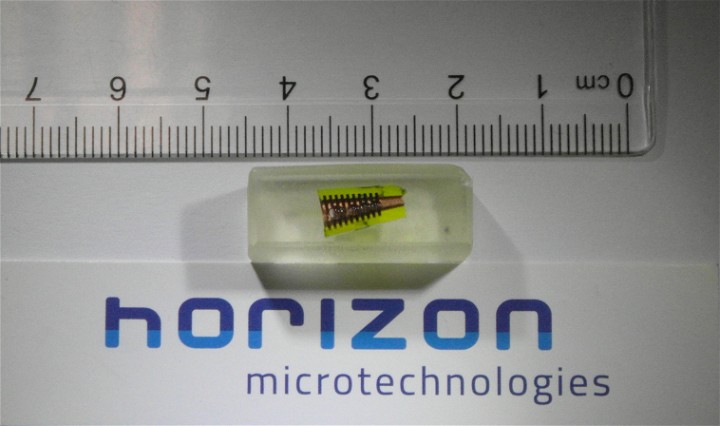
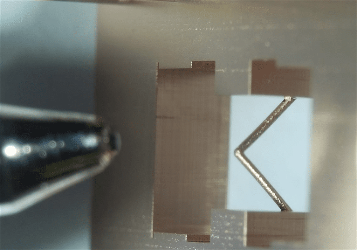
Environmental Test Experience For An Antenna Application
The device being tested is a hybrid structure that combines the mechanical robustness of an AM bare metal structure with the electronic performance of a printed electronic AME structure inlay.
Concepts
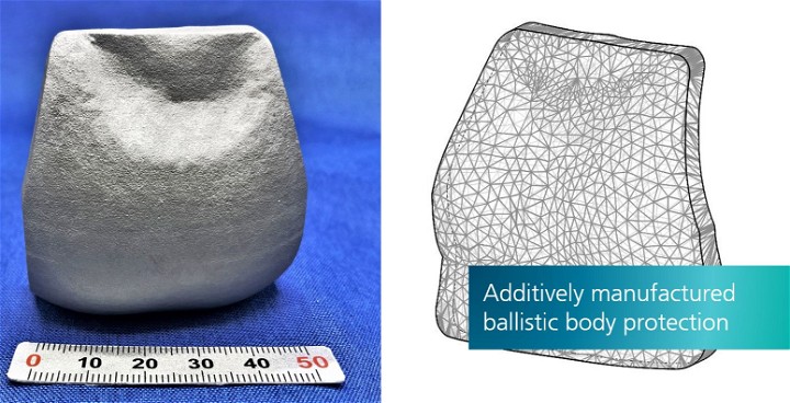
Additively Manufactured Ballistic Body Armor
Modern shaping processes such as Additive Manufacturing (AM) make it possible to produce customized body armor for ballistic protective vests. These consist of textile, metallic, ceramic or composite ...

Historic E-guitar Meets AME
The exhibition presents how AME technology fulfills distinctive design and shape necessities, transforming current structures into electric ones.
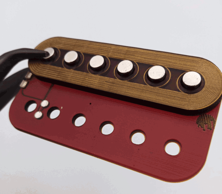
Historic E-guitar: Idea Pickup AMEfication
In the final episode of the Historic E-Guitar series, we continue our exploration of pickup amplification in electric guitars. Get ready to discover the remarkable technological advancements and ...

J.A.M.E.S Coin NFC On AME In 3D Ceramics
For the first time the J.A.M.E.S Coin Design is transformed into a new material and process concept. The Fraunhofer IKTS at Dresden used their process knowledge in additive ceramics to realize the ...

System In Package (SIP)
The goal is to create a reliable and efficient way to design and manufacture system-in-package (SIP) devices. In contrast to traditional approaches, it is intended to avoid wire bonding processes. ...

RF Synthesizer - 3D Heterogeneous Integration
The goal of this AME story is to develop a guideline towards a highly integrated electrified volume of arbitrary shape. It is intended to leave the flat PCB formfactor behind and fit the desired ...

J.A.M.E.S Coin NFC In AME
The purpose of this design remains to be purely educational. It is meant to give a brief introduction on the full potential of the AME technology by embedding the COTS components of the J.A.M.E.S ...

Induction Motor Design Concept
The design shows the concept of an additively manufactured induction motor. The vision behind this is to 3D-print functional electric motors. Electric motors are most commonly manufactured by winding ...

Advanced AME Equipment Enabling Surface Part Mounting Substrates
FPM-Trinity is not only for the creation of bare boards made with dielectric resin and conductive ink but also for the creation of boards with SMT parts.

RF-Interface Elements
High-frequency AME designs demand precise RF signal handling, with a focus on critical RF interfaces and simulation for impedance control and frequency matching.

AME Innovation: Harnessing The Power Of ESP-EYE
The ESP-EYE, provided by ESPRESSIF, is a development board designed for image recognition and audio processing, making it suitable for various AIoT applications.

3D AME Ferrite Ring Core Coil
This article showcases the continuous efforts of the J.A.M.E.S engineering team in creating a focused AME coil element. The aim is to integrate a ferrite ring core to enhance inductivity. The ...

RF-connector To AME Microstrip
In the field of advanced electronics, Additive Manufacturing Electronics (AME) has emerged as a cutting-edge design approach, enabling the seamless integration of RF interfaces using Southwest ...

Historic E-guitar: Idea Pickguard AMEfication
We are thrilled to share further insights and updates on episode two of our Historic E-guitar Meets AME. Join us again as we showcase our dedication and innovative spirit.

Educational AME-Motor
Experience our demonstrator assembly with various AME Motors and Brushless Motor controller designs, witnessing the industry's innovative advancements and AME's transformative role.

Populating DragonFly IV AMEs
Find out how to populate external COTS components on your AME design

Hardware Cyber Security By AME
The goal is to describe the potential benefits of AME in aspects of hardware cyber security. Nowadays protection against industrial espionage for electronic devices takes more and more ...

One Print-Job In Two Parts
Standard model for die placing that split for 2 print-jobs and printed one on top of the other. We saw the opportunity in creating SIP by Nano-Dimension printer, it makes the SIP faster, create high ...

Simultaneous Manufacturing And Co-Sintering
To allow the integration of the functional materials also inside the component, which results in a higher degree of freedom concerning the design, simultaneous manufacturing is used.

Sequential Component Manufacturing
In order to integrate additional functionalities within one component, different materials or material mixtures have to be combined. This poses an enormous challenge in thermal co-processing, making ...

Sintering As A Feature Of The Process Chain
Sintering is an additional process step in comparison to standard polymer based electronic manufacturing.

Design Data For DragonFly IV
Get access to all the required data to start your own design process for the DragonFly IV system.


Infrastructure For DragonFly IV
Get an overview of the technology the DragonFly IV system is using to print your vision for AME.

Slicing For DragonFly IV
Do you want to print your design after finishing it? Find out how to slice it into a print job.

Tutorials To Learn About AME
Do you want to get involved and start your own AME experience? Do you want to design and realize exciting AME structures, but you are not sure how to do it? Then you came to the right place. The ...

Lumped AME Filters
The goal is to derive a methodology to generate lumped AME element filters consisting of AME coils and AME capacitors. The process should be as automatic as possible and ideally result in a ...

AME Drone
Designing a fully functioning drone is a quite challenging task. Due to their operation conditions, the usual requirements for the electronics include being lightweight, low power consumption and ...
Publications

Exploring Multi-Material Printing For Rapid Prototyping Of Multilayer Hybrid Ceramic Components
This technical article is created by following authors: Prashantkumar Pandey and Steffen Ziesche, Fraunhofer Institute for Ceramic Technologies and Systems IKTS Lopec 2024 Poster Session

Revolutionizing Display Manufacturing: The Impact Of XTPL’s Ultra-precise Dispensing Technology
Advancements in high-tech display technology are revolutionizing the market with Ultra-HD and 8K screens now available, pushing the boundaries of picture quality. The demand for precise manufacturing ...

Long Term And Cryogenic Endurance Of FPC Interconnection Approaches
This technical Article is created by following Authors: Alois Friedberger, Andreas Helwig Airbus CRT, Central R&T, Taufkirchen (Munich), Germany Patrick Hornung ...

Durability Investigations Of 3D Printed Electronics Towards Aeronautic-inspired Environmental Loads
Together with AIRBUS Central Research and Technology J.A.M.E.S engineering established collaboration activities in field of 3D printed electronics with interest for aeronautic usecase. AME printed ...

The Mastery Of UPD Technology In Nanomaterial Dispensing For Advanced Manufacturing
XTPL Ultra Precise Dispensing (UPD) technology is a system, standing for precision and innovation, that seamlessly integrates into both existing and prospective production lines. The UPD system, ...

Understanding Flexible Hybrid Electronics: An In‑depth Exploration
Flexible Hybrid Electronics: an introduction 〰️➰ ➿ Traditional electronic devices are limited in their application due to their inflexibility and weight. In contrast, Flexible Hybrid ...

Design And Fabrication Of A Plastic-Free Antenna On A Sustainable Chitosan Substrate
"Design and Fabrication of a Plastic-Free Antenna on a Sustainable Chitosan Substrate" by I. Marasco et al., 2023.

Exploring The Production Process Behind Semiconductor Fabrication
🔬 Curious about the production process behind semiconductor fabrication? 🌟 Check out our insightful article, where we delve into the intricacies of manufacturing semiconductors and highlight ...

Flexible Quantum-Dot Light-Emitting Diodes Using Embedded Silver Mesh Transparent Electrodes Manufactured By An Ultraprecise Deposition Method
Flexible substrates with transparent conductive electrodes (TCEs) are essential components of organic-light-emitting diodes (OLEDs). However, Indium tin oxide (ITO), the prevailing transparent and ...

Printed Electronics For Highest Frequencies: 6G Wireless Communication Technology And Millimeter Wave Radar
by Dr. Uwe Partsch, Fraunhofer IKTS (Fraunhofer Institute for Ceramic Technologies and Systems IKTS) Ceramic substrate materials and adapted thick-film pastes and inks can make a significant ...

XTPL's Innovative High-Resolution Dispensing Technology For Advanced Electronics Manufacturing
XTPL team presents a comprehensive article concerning its own, disruptive technological solutions for extremely high-resolution dispensing of functional materials for manufacturing the next ...

Cube Satellites: Paving The Way For The Future Of Space Activities
Exploring the vast expanses of space has always captivated human imagination, driving us to uncover its mysteries and push technological boundaries. In recent times, Cube Satellites have emerged as ...

A Research Study: Advantages Of XTPL Delta Printing System
Authors of the article "All-Printed ZnO Nanowire based High-Performance Flexible Ultraviolet Photodetectors" prominently features the extensive use of the Delta Printing System in its research ...

TactoTek And Essemtec: Printed Electronics (Case Study)
Printed electronics have gained significant acceptance in the electronics industry due to its versatile functionalities in various manufacturing processes.

Signal Transmission Behavior Of Conductive Filaments In The Context Of Fused Filament Fabrication (FFF) Procedure
Explore David Neuhart's Bachelor Thesis on signal transmission in fused filament fabrication, comparing conductive filaments and variations in signal behavior.
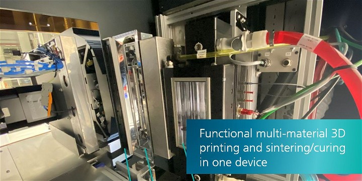
Functional Multi-Material 3D Printing And Sintering/Curing In One Device
Dr.-Ing. Steffen Ziesche of Fraunhofer IKTS presents advancements in ceramic multilayer manufacturing to new heights in this insightful presentation.
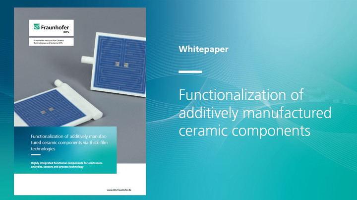
Functionalization Of Additively Manufactured Ceramic Components Via Thick-film Technologies
by Lars Rebenklau, Fraunhofer IKTS (Fraunhofer Institute for Ceramic Technologies and Systems IKTS) The whitepaper provides a simplified overview of the basics of thick-film technology and its ...

Explaining The CerAM Vat Photo Polymerization Based On JAMES Coin Design
Article by Eric Schwarzer-Fischer, Nadine Lorenz and Uwe Scheithauer, Fraunhofer IKTS (Fraunhofer Institute for Ceramic Technologies and Systems IKTS)

Introduction To CerAMfacturing At Fraunhofer IKTS
This article provides you a full insider perspective with expertise and competence behind 3D ceramic technology by Uwe Scheithauer and Lars Rebenklau, Fraunhofer IKTS (Fraunhofer Institute for ...

Design And Performance Of AM In-Circuit Board Planar Capacitors
Sokol D., et al. showcase AM-based planar capacitors with diverse geometries, layers, and exceptional performance across multiple frequencies.

Design Parameters For The Additive Production Of Electronics
The research paper was prepared by Tim Frank, with support provided by J.A.M.E.S. Tim Frank took the lead in preparing the paper, showcasing his expertise and dedication.

Compact Multilayer Bandpass Filter
Compact Multilayer Bandpass Filter Using Low-Temperature Additively Manufacturing Solution This publication was written by Li M., et al. in 2021, and present an additively manufactured bandpass ...

Additively Manufactured Millimeter-Wave
Additively Manufactured Millimeter-Wave Dual-Band Single-Polarization Shared Aperture Fresnel Zone Plate Metalens Antenna This publication was written by Zhu, J., et al. in 2021 and presents the ...

Introduction To AME And What It Can Do For You
The research paper was prepared by the J.A.M.E.S. engineering team and primarily focuses on the advantages of Additively Manufactured Electronics (AME) over traditional printed circuit board (PCB) ...

Investigation Of Material Models For Fiber Reinforced Plastics
This master thesis was prepared by Michael Grüfelder, with support from J.A.M.E.S. Michael took the lead in its preparation, showcasing expertise and dedication to the research process.
News
Horizon Successfully Manufactures Corrugated Horn Antenna
Horizon has printed a funnel-shaped horn with internal corrugations, which has subsequently been coated using its HMT-Metal coating process.

Horizon Demonstrates The Effectiveness Of Its HMT-Metal Coating Process For Plastic Micro AM Parts : A Case Study
Proof of effectiveness of HMT-Metak coating process for making high frequency D-Dand horn antenna via 3D printing

Optimizing Component Design Via Coated Micro-AM For Exacting Precision Engineering And Semi-Conductor Applications
The metallization of micro-AM templates represents a highly intriguing and disruptive advancement in the realm of micro passive microwave & mm-wave component production, including parts such as ...

Horizon Invests In In-House Micro AM Machine From BMF & Now Offers Truly Vertically Integrated 3D Microfabrication Service
When producing exceptionally precise and tight tolerance parts and components, the significance and added value of a vertically integrated development and manufacturing partner becomes paramount.
Horizon Adds Metal Coatings To Its Portfolio Of 3D Microfabrication Technologies
Horizon is now also able to add copper metal coatings to polymer micro-AM and other micro structures.

Horizon Brings The Power Or Micro-AM To The Production Of ESD Sensitive Parts
Bringing the Power or Micro-AM to the Production of ESD Sensitive Parts

Benchmarking Metal Coating And Metal Fabrication Technologies For Polymer Micro Parts: A Comparative Analysis
This article benchmarks different metal fabrication processes, and compares them with the newly launched metal coating technology commercialized by Horizon.
The Basics Of Horizons Proprietary Coatings For Plastic Micro AM Parts
Horizon Microtechnologies has developed proprietary coating processes for plastic micro AM parts, that allows new areas of industry to benefit from the power, flexibility, agility, and design freedom ...

Horizon Launches Breakthrough Technology At Formnext 2022
Horizon Microtechnologies commercially launches its ground-breaking proprietary coating process.

Insights From J.A.M.E.S At Embedded World 2024
At Embedded World 2024, the J.A.M.E.S team focused on the latest trends and potential partnerships driving the advancement of Additively Manufactured Electronics (AME). Navigating through the ...

Smart Tyre Won The OE-A Best Publicly Funded Project
JOANNEUM RESEARCH MATERIALS is pleased to announce that our "Smart Tyre" won at LOPEC the "Best Publicly Funded Project Demonstrator" award. A quick glance at your mobile phone or bike computer and ...

Semiconductor Packaging State Of The Art
This article will briefly describe the semiconductor packaging industry. It will include an overview of electronic packaging and semiconductor packaging, highlighting key moments in the history of ...

Witnessing The Future Of 3D Printing Electronics With FPM-Trinity
In the last week of January 2024, a significant event took place in Japan. Our CEO, Andreas Müller, and Alexandre Schäfer, our Head of Marketing and Sales, attended the 38th NEPCON in Tokyo, ...

Advancements In Microelectronics: DARPA's Pioneering Initiatives
The recent introduction of the Additive Manufacturing of Microelectronic SystEms (AMME) program by the Defense Advanced Research Projects Agency (DARPA) shows a significant advancement in Additively ...

Exploring Electronics and 3D Printing Projects
Welcome to J.A.M.E.S, pioneer in 3D printing engineering projects about additively manufactured electronics. Are you ready to discover the next level of electronics manufacturing? We are dedicated to ...

Exploring Electronics 3D Design and Printing
The design process of 3D printed electronics encompasses several stages, leveraging the integration of 3D digital designs, specialized 3D printing software and advanced additive manufacturing ...

J.A.M.E.S: Advancing 3D Printing Electronics to the Next Level
A groundbreaking advancement has emerged in electronics production with 3D printing technology for companies. J.A.M.E.S is dedicated to unlocking the full potential of additively manufactured ...

Flexible Conductive Inks: A Pillar In Electronics Innovation
Flexible conductive inks enable electronics devices to revolutionize industries from healthcare to automotive. Learn about their properties, the benefits they bring, their applications, substrates ...

The Evolution Of Organic Electronics In The Electronics Sector
Organic electronics represent a transformative shift in the electronics industry, departing from traditional inorganic materials like silicon and moving towards organic materials that offer ...

J.A.M.E.S Team's Experience At LOPEC 2024
On March 6 and 7, 2024, the J.A.M.E.S team had the opportunity to attend LOPEC 2024 in Munich. The team's objective was to gain insights, gather information, and establish and expand our network in ...

AI Impact On Semiconductor Manufacturing & Electronics Component Design
Artificial Intelligence (AI) is reforming in various industries, and the semiconductor manufacturing sector is no exception. AI's integration into semiconductor manufacturing and the design processes ...

Leading The Future In 3D Printing Technology And Manufacturing
Welcome to J.A.M.E.S, a pioneer among 3D manufacturing companies, where creativity combines with practicality in the field of 3D print manufacturing. At J.A.M.E.S, we specialize in 3D printed ...

3D Printing & Electronics: Fusion With New Materials
The combination of 3D printing and electronics has brought about a new era in manufacturing, enabling the production of intricate electronic components with remarkable efficiency and adaptability. ...

J.A.M.E.S: Your 3D Printing Consultancy Services
Welcome to J.A.M.E.S, where we offer professional consultancy services in the field of 3D printing. Our team is equipped with extensive knowledge in 3D printing electronics ...

3D Printing And Sustainable Manufacturing
The 3D printing industry once primarily focused on rapid prototyping, has now expanded into numerous sectors, emphasizing eco-friendly practices. This article explores the impact of 3D printing on ...

Why should I print PCBs instead of manufacturing them traditionally?
Printing PCBs (Printed Circuit Boards) offers several advantages over traditional manufacturing methods (banner picture by pngtree.com):

Can I combine inkjet printing process and nanotechnology for 3D printed electronics?
Tell me more about it.

Pioneering Additive Manufacturing and Prototyping Solutions
Begin your journey of innovation with J.A.M.E.S, your dedicated ally in the forefront of 3D printing and rapid prototyping. Our expertise, precision, and dedication to excellence set us apart in the ...

J.A.M.E.S And Our Diverse 3D Printing Materials
J.A.M.E.S represents the midpoint of groundbreaking developments in 3D printed electronics and materials. Our collaborative approach includes a range of specialties, focusing on the development and ...

First Community-Centric Collaboration In Sustainable Manufacturing
At J.A.M.E.S, we believe that the future of innovation is in our 3D printing network, a community-driven ecosystem with every member playing a vital role in promoting 3D printing technologies and ...

The Advantages Of 3D Printed Electronics
The combination of 3D printing and electronics is changing fundamentally manufacturing and design, opening up new possibilities. This approach enables the creation of complex designs and unique ...

What Software To Use For 3D Printing
3D printing is an innovative technology that creates three-dimensional objects from digital models. It has revolutionized industries such as manufacturing and healthcare by layering materials based ...

University Of Stuttgart & KIT Test Delta Printing And XTPL Tech For New Application
We are thrilled to announce that the Delta Printing System and XTPL Ultra-Precise Deposition technology were recently tested for a new application by our partners from the University of Stuttgart and ...

Shifting Gears In 3D Printing: Application Over Equipment
In the past, the industry primarily concentrated on producing adaptable equipment with the aim of gaining consumer acceptance. However, there is now a shift towards development that is focused on ...

XTPL's Pioneering Role In The UltraSense Project Under HORIZON Program
XTPL S.A., a partner of J.A.M.E.S, has recently received a European grant for their involvement in the UltraSense project under the HORIZON program. This project carried out in collaboration with an ...

Ease Of Use Meets Advanced Technology: The XTPL Delta Printing System!
With its combination of cutting-edge technology and user-friendly design, the XTPL Delta Printing System allows users to quickly start advanced projects and make a significant impact in their ...

XTPL Delta Printing System: Redefining Precision & Versatility!
Experience unparalleled precision and versatility with the XTPL Delta Printing System! Incorporating XTPL Ultra-Precise Dispensing Technology, this cutting-edge printer offers micron-level accuracy ...

FPM-Trinity - World Premiere At The INTERNEPCON JAPAN 2024 In Tokyo
FUJI Unveils FPM-Trinity: Empowering Industrial Innovation in 3D Electronics Printing at INTERNEPCON JAPAN 2024 FUJI, one of our partners in our network and a trailblazer in cutting-edge technology, ...

Key Moments & Insights: 2023 European AME User Forum
Join us in revisiting the highlights of the 2023 European AME User Forum, an event that marked a significant milestone in Additively Manufactured Electronics (AME). For an in-depth look at this ...

Groundbreaking Research In Printed Electronics Using Voltera Dispensing Systems
See some of the diverse applications being developed using NOVA and V-One. Learn about printing biomedical tattoos, electrospray emitters, structural health monitoring, smart facemasks and more.

High Frequency Solution-processed Organic Field-effect Transistors With High-resolution Printed Short Channels
Our colleagues from XTPL, Mateusz Łysień and Łukasz Witczak, collaborated with Tommaso Losi, Pietro Rossi, Paola Moretti, Chiara Bertarelli, Mario Caironi from Istituto Italiano di Tecnologia and ...
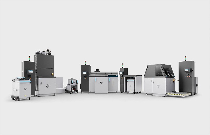
Advancing Additive Manufacturing: HP's Breakthroughs In Polymer And Metal 3D Printing
HP Inc.'s presentation at Formnext, the world’s largest trade fair for additive manufacturing, highlighted significant advancements in polymer and metal 3D printing, which are highly relevant to ...

Enhancing Smart Ski Goggles With Additive Manufacturing Electronics (AME) Technology
The innovative integration of Augmented Reality (AR) in ski goggles by Rekkie marks a leap forward in skiing technology. These goggles not only display essential data like speed and altitude but also ...

J.A.M.E.S And Friends Interview Series: Innovations In AME With Fraunhofer IKTS
In this episode of the J.A.M.E.S and Friends interview series, Philip Stoten from Forbes had a discussion with Uwe Scheithauer from Fraunhofer IKTS to explore advancement developments in AME. Uwe ...
How Additive Manufacturing Is Transforming Healthcare
Introduction: The medical industry is on the brink of a transformation, with Additive Manufacturing (AM) leading the charge. A recent article on BotFactory, titled "The Evolution of Medical ...

Innovation Vs. Tradition: AME Vs. Conventional Manufacturing
The comparison between Advanced Manufacturing Engineering (AME) technologies, such as Additive Manufacturing (AM), and conventional manufacturing methods reveals distinct differences in capabilities, ...

NScrypt's Innovation: Multi-material Mixing Valve For 3D Printing
nScrypt, a pioneering US-based company, has recently announced a significant breakthrough in 3D printing technology with the granting of a patent for a novel mixing valve. This valve promises to ...

Voltera: Removing Barriers In Printed Electronics
Explore the future of electronics with Voltera. We catalyze innovation by removing barriers to entry in the printed electronics industry with our user-friendly electronics prototyping platforms — ...

Nano Dimension Introduces INSU 200
Nano Dimension unveils INSU 200, a game-changing material reshaping AME. Leading in innovation, Nano Dimension achieves TRL 6, setting new industry standards.

J.A.M.E.S Partners With APES Forge Strategic Partnership To Boost AME Innovation
In a significant development for the world of Additively Manufactured Electronics (AME), J.A.M.E.S (Jetted Additively Manufactured Electronics Sources) is proud to announce a strategic partnership ...

J.A.M.E.S And NScrypt Partner To Propel AME Innovation
J.A.M.E.S (Jetted Additively Manufactured Electronics Sources) proudly announces a partnership with nScrypt, manufacturer of the Factory in a Tool (FiT) series of high-precision motion platforms for ...

Breaking Update: J.A.M.E.S And XTPL Redefining 3D Manufacturing
J.A.M.E.S and XTPL's partnership has reached a milestone with prototype production to assess RF and electrical capabilities.

J.A.M.E.S And Friends Interview Series: Exploring AME Innovation With Fuji
In our ongoing commitment to fostering collaboration and knowledge exchange with J.A.M.E.S, Ryojiro Tominaga from Fuji participated in the 'J.A.M.E.S and Friends Interview Series.' In this episode, ...

J.A.M.E.S Coin With NFC Functionality
In this article, we like to showcase our groundbreaking product, the J.A.M.E.S Coin, featuring cutting-edge NFC functionality and Additively Manufactured Electronics (AME).

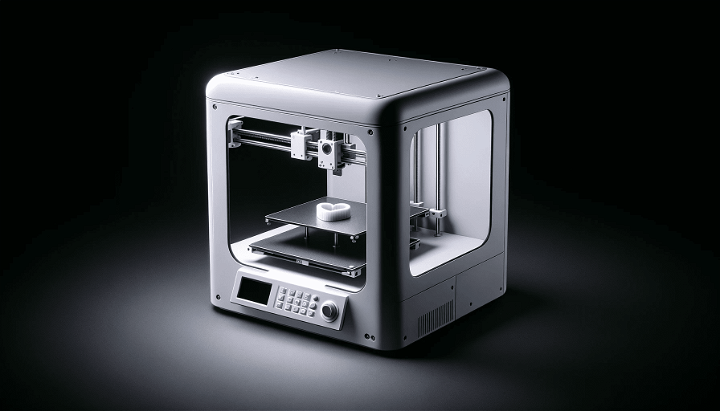
The Energy Consumption Of 3D Printers
The impact of 3D printing technology on the environment has raised concerns regarding its electricity consumption. This article aims to examine the energy usage of 3D printers and evaluate their true ...

The Steps Of AME Into A Qualified Product
In this article, we delve into the significant steps to propel AME towards practical products with J.A.M.E.S's tailored checklist for AME service providers. It's designed to facilitate successful ...

From Concept To Qualified Product
The utilization of additive manufacturing electronics (AME) presents a vast potential for upcoming use cases and products that leverage its capabilities. By combining the power of traditional ...

J.A.M.E.S & Nano Dimension Tech Talk Highlights
We are excited to showcase the remarkable moments from our highly collaborative Tech Talk event. This event brought together experts and visionaries to explore AME's future.

AME And Micro-AM Tech Day Event
Tech-Day: Tipping The Scales Of Innovation Through Micro-AM And Additively Manufactured Electronics On Tuesday, April 27th, Nano Dimension hosted a technology day event, where it was showcased the ...

Where Is 3D Printing Used?
In recent years, 3D printing has significantly transformed industries by expanding manufacturing and design capabilities. It offers versatility for both small-scale prototypes and large-scale ...

J.A.M.E.S And TH-Rosenheim Foster Collaboration
Recently, J.A.M.E.S had the opportunity to visit TH-Rosenheim and engage in a special talk with Prof. Dr.-Ing. Matthias Winter within their remarkable labs. The conversation revolved around our ...

How To Design AME: An Overview
This article aims to provide a comprehensive overview of Additively Manufactured Electronics (AME) and its significance in the world of additive manufacturing.

The Next Level Of 3D Printing
In March 2023, Formnext Magazine published an article written by Thomas Masuch about the potential of 3D printing of electronics for industrial use. It highlights the gradual progress being made ...

Historic E-guitar: Introduction And Idea Behind
Welcome to our captivating journey of transforming a non-working vintage masterpiece guitar into a playable instrument while preserving its original body and style. In this episode, get ready to ...

Which 3D Printer Is More Sustainable?
When it comes to 3D printing, choosing an environmentally friendly option is key. In this article, we'll compare the sustainability of three popular models - Ultimaker S5, Prusa i3 MK3S+, and ...

J.A.M.E.S And Fuji Corporation Join Forces To Drive Innovation In 3D Manufacturing
J.A.M.E.S, the collaborative community for additively manufactured electronics (AME) development, is pleased to announce its partnership with Fuji Corporation, a leading manufacturing company known ...

J.A.M.E.S Partners With The Manufacturing Technology Centre (MTC) To Advance And Expand The Network Of AME
J.A.M.E.S (Jetted Additively Manufactured Electronics Sources), a leading company forefront of AME technology, is proud to announce a partnership with Manufacturing Technology Centre (MTC), an ...

Is 3D Printing Eco-friendly?
3D printing has revolutionized the world of manufacturing by enabling businesses and individuals to create complex products with ease. However, as we continue to strive for more sustainable practices ...

J.A.M.E.S And Global Inkjet Systems Partnership
J.A.M.E.S And Global Inkjet Systems Partner To Speed Up The Development Of Additively Manufactured Electronics (AME) J.A.M.E.S “Jetted Additively Manufactured Electronics Sources,” the ...

J.A.M.E.S Partnership With HeliguyTM Lab
J.A.M.E.S announces a partnership with heliguyTM Lab to develop emerging technologies Munich, Germany, December 15th, 2022. J.A.M.E.S stands for “Jetted Additively Manufactured Electronics ...

TH- Rosenheim University Students Visit J.A.M.E.S Office
Last week, J.A.M.E.S was honored to receive a delegation of ten students and their professors from TH-Rosenheim University. The visit started off with a welcome by Andreas Salomon, the Chief ...

The Potential Of 3D Printed Electronics
In recent years, 3D printing has changed a lot of manufacturing processes across various industries. One of the most exciting advancements in this field is the development of 3D-printed electronics.

Can A 3D Printer Print Electronics?
Over time, 3D printing has transformed manufacturing processes in various industries. It's a pioneering technology that has progressed from fabricating simple plastic prototypes to creating complex ...

Exploring The Future Of 3D Electronics With Additive Manufactured Electronics (AME)
As the world of technology continues to advance at a rapid pace, one area that is showing tremendous potential for growth and innovation is the field of electronics manufacturing. The emergence of 3D ...

J.A.M.E.S And XTPL Join Forces In A Groundbreaking Collaboration
J.A.M.E.S, a frontrunner in the field of Additively Manufactured Electronics (AME), and XTPL, an emerging leader in ultra-precise printing of nanomaterials, have initiated a collaborative project ...

Which 3D Printer Is Best
The innovation of 3D printing has significantly transformed the way we approach manufacturing, design, and prototyping. The market offers an abundance of options that can be overwhelming when ...

What 3D Printers Can Do
The field of manufacturing has been transformed by the introduction of 3D printing technology. Thanks to this cutting-edge innovation, it is now possible to create intricate designs and structures in ...

Why 3D Printing Is The Future
Due to its cost-effective and expedited production of friendly tailored, it comes as no shock that 3D printing has emerged as the leading force in modern-day manufacturing practices.

Electronics Printing
The printing of three-dimensional objects is being used commercially by more and more industries.

Silver Nanowires
Silver nanowires are one-dimensional structures with a diameter typically less than 100 nm and a length in the micrometer range. They are widely studied in the field of nanotechnology due to their ...

3D Printing Materials Guide
The technology of 3D printing, or additive manufacturing, is an advancement that permits the production of three-dimensional objects through digital data. An essential determinant in this process ...

An Introduction To 3D Printing
3D printing is an advanced manufacturing technology that has revolutionized how products are designed, developed, and produced. This technology, also known as additive manufacturing, involves ...

Exploring The Different Processes In 3D Printing
3D printing is a groundbreaking technology that has revolutionized the manufacturing industry, allowing for the creation of complex objects with intricate geometries and design features. There are ...
Webinars

Explore The Impact Of AME On The Bare Die Packaging Industry Webinar Recap
We extend our heartfelt gratitude to all attendees who joined us for an insightful webinar led by our esteemed expert, Nikita Rybalka. For those who couldn't attend or wish to revisit the valuable ...

Printing Biomedical Sensors With Ag/AgCl Ink
A recap of our webinar on biomedical sensors printed with silver silver-chloride ink using NOVA.

AM Process For Low Impedance Electronics Webinar Recap
Thank you to everyone who joined us for the webinar, "AM Process for Low Impedance Electronics." We're thrilled to share that the event was a resounding success, drawing in a diverse and engaged ...

A Tool For Every Additive Electronics Project Webinar Recap
We appreciate the participation of all those who took part in our recent webinar, led by Jesus Zozaya from Voltera. Your active involvement was a key factor in making it a success. If you didn't have ...

FPM-Trinity: 3D Printing & CAD Flow Webinar Recap
In our recent webinar held on October 26, 2023, Naohiko Hiramatsu from FUJI Corporation shared insightful knowledge about FPM-Trinity technology and its profound impact on the industry.

Advantages Of 3D Printed Electronics Webinar
First and foremost, we extend our sincere thanks to all those who joined us for the exciting webinar led by Jason Benoit from nScrypt. Your active participation made the webinar a success. For those ...
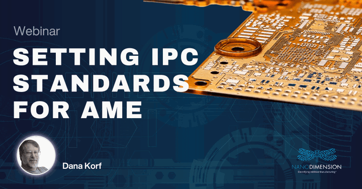
Setting IPC Standards Webinar
We are delighted to share the exciting news of the recent webinar, "Setting IPC Standards - How Nano Dimension is shaping the future of AME"

Introduction Of Advanced All In One Machine For AME And SMT Webinar
We are delighted to share the exciting news of our successful webinar, 'Introduction of Advanced All in One Machine for AME And SMT'.

Innovative Packaging With AME Technology Webinar
Our gratitude goes out to all the attendees who made our August 24th webinar, 'Innovative Packaging with AME Technology,' a resounding success. Your participation added value to the session as we ...

Design Parameters For Additive Production Of Electronics Webinar
We are grateful to all the participants who joined us on August 3, 2023, for our webinar "Design Parameters for Additive Production of Electronics." The webinar was a success and we couldn't have ...

Exploring AME Webinar
We are delighted to share the exciting news of our successful webinar, "Exploring AME: From Concept to Qualified Product." This event delved deep into the field of Additively Manufactured Electronics ...

How To Design AME With CST Studio Suite Webinar
We would like to express our sincere gratitude to all the participants who joined us for the informative webinar on July 20th "How to Design AME with CST Studio Suite." It was a fantastic opportunity ...
Tools
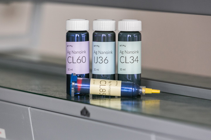
XTPL High-Performance Nanoinks & Nanopastes
XTPL's High-Performance Materials can significantly enhance the functionality of electronic devices, enabling new applications and features previously not possible with traditional printing ...

XTPL High-Performance Materials Applications
XTPL Nanoinks offer precision, efficiency, and versatility, reducing costs and waste in nanotechnology for diverse applications.

About FPM-Trinity
FPM-Trinity, an innovative AME system by FUJI, a leading pick & place manufacturer, combines AME and SMT to automate electronic board creation.

DragonFly IV To LDM
This script is a tool that allows you to perform operations on a PCBJC files.

DragonFly IV Real Ink Status
This script is designed to perform automated monitoring and alerting for liquid levels in tanks.

DragonFly IV Logger
We're excited to introduce our latest script that will help you monitor and analyze your 3D printing jobs more effectively. This script is designed to work seamlessly with your 3D printer's log ...

DragonFly IV Resolution Changer
We're thrilled to introduce a new script designed to enhance your DragonFly 3D printer experience. This script simplifies and automates several steps in your workflow, from project file management to ...

Dragonfly IV Logs Collector Tool
DragonFly-IV (DF-IV) is an AME printer manufactured by the Nano-Dimension company. This tool collects logs created by the printer and puts some parameters to the excel file (.csv). Also, it collects ...

DragonFly IV Alignment Of Print Jobs
The tool is designed to facilitate the alignment and positioning of print jobs. It provides the following features.

Design AME Coils Tool
You are not sure about how many windings you need to get the right inductivity? Check out our AME coils tools to get some answers.

Design AME Capacitors Tool
If you plan to integrate capacitors directly into your AME structure, here you will get help to find the right dimensions.