Breadboards Vs. PCBs: Definitions, Materials, Costs, Benefits, And Applications
Concept
This AME design has the status of concept. A first design concept is established, a complete explanation of the targeted functionality is included, and the targeted printer technology has been provided.
Choosing the right development platform for your electronics project can significantly impact its efficiency and success rates. Breadboards and printed circuit boards (PCBs) each offer unique advantages suited to different stages of development. This blog will explore the key differences between the two in terms of definitions, materials and substrates, manufacturing processes and costs, as well as benefits and applications, helping you make informed decisions for your electronics projects.
Definitions
What are breadboards?
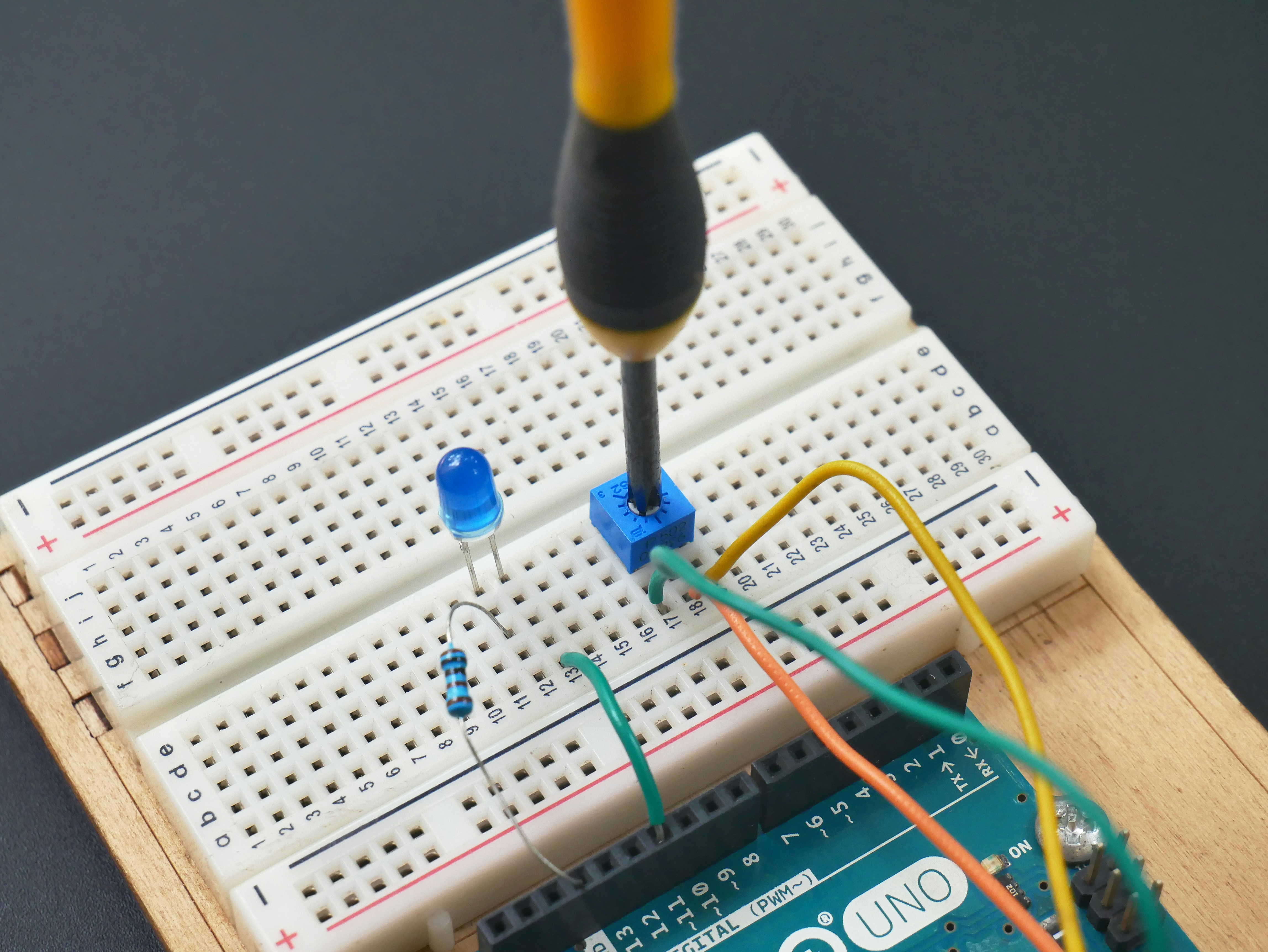
Breadboards, also known as protoboards, consist of a perforated plastic board with a grid of holes where components can be inserted. The central area of the breadboard is divided into rows, each with internal electrical connections, allowing components placed in the same row to be connected without soldering. Separate vertical columns, known as power rails, line the outer edges to facilitate easy power distribution across the board.
A breadboard with components connected to an Arduino Uno board (Image: Vishnu Mohanan)
What are PCBs?
Printed circuit boards mechanically support and electrically connect electronic components through conductive tracks, pads, and other features. PCBs are a crucial component in any electronic device.
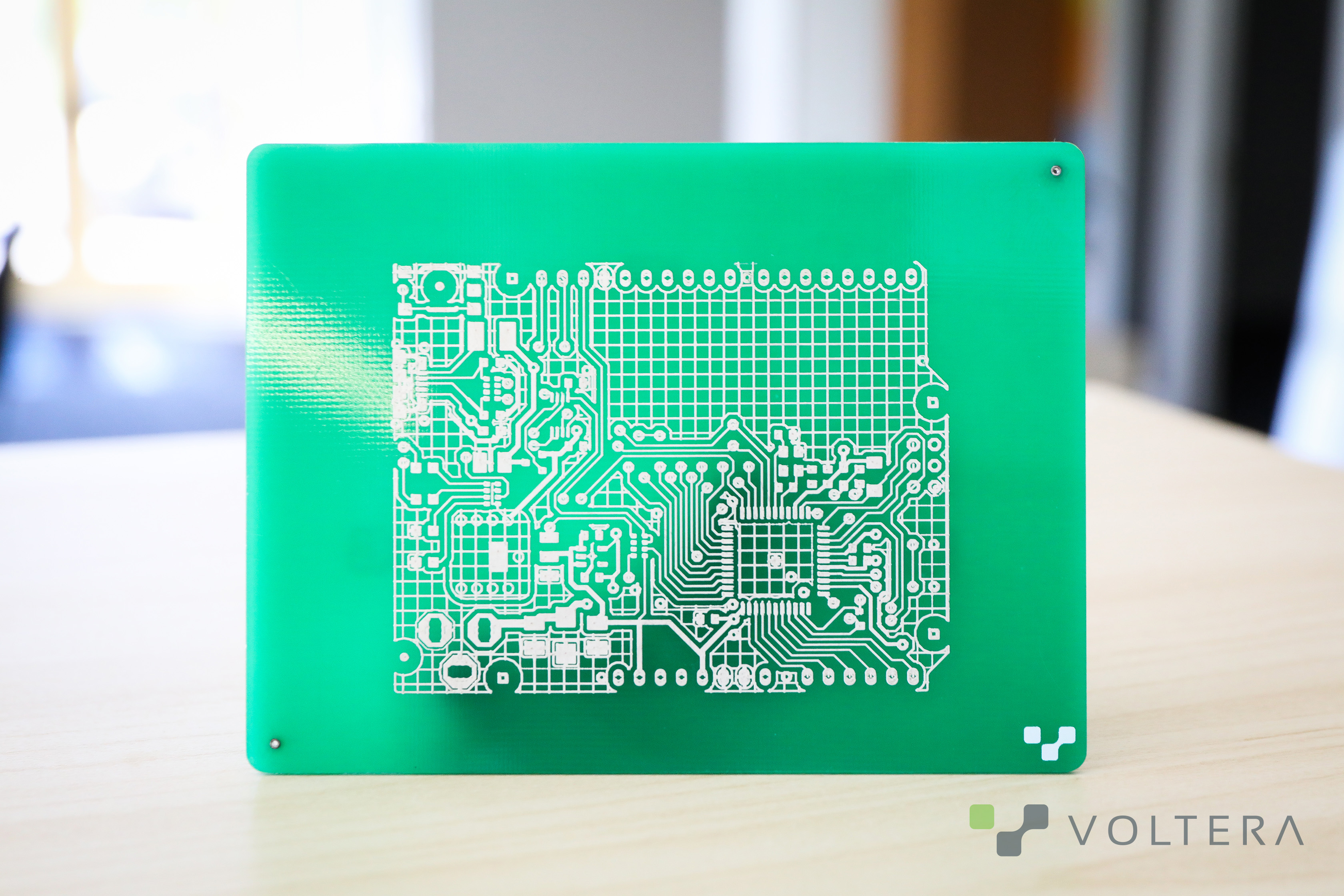
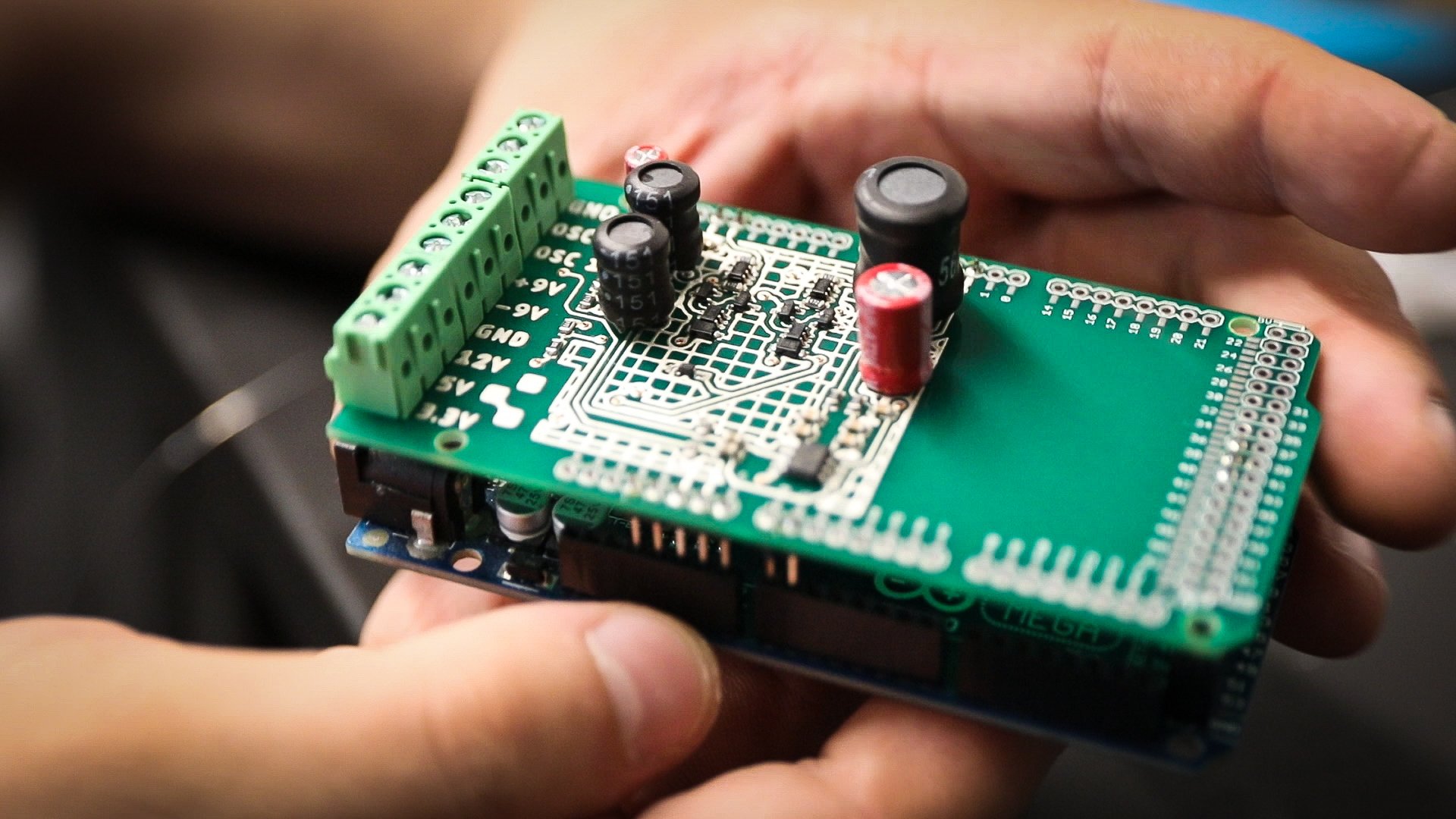
An Arduino Leonardo printed circuit done with V-One
Types of PCBs
In modern electronics, single-layer, double-layer, and multi-layer PCBs are common, each offering varying levels of complexity and functionality. Among these, several types of PCBs stand out for their popularity: breakout boards, template boards, and development boards.
Breakout boards
Breakout boards are compact PCBs designed to provide easy access to the pins of an integrated circuit or other components. They "break out" the connections from a single component or chip to a more manageable layout, typically with larger, more accessible pins. This design makes it easier to integrate specific components into your projects without dealing with very small or densely packed pins.
Template and development boards
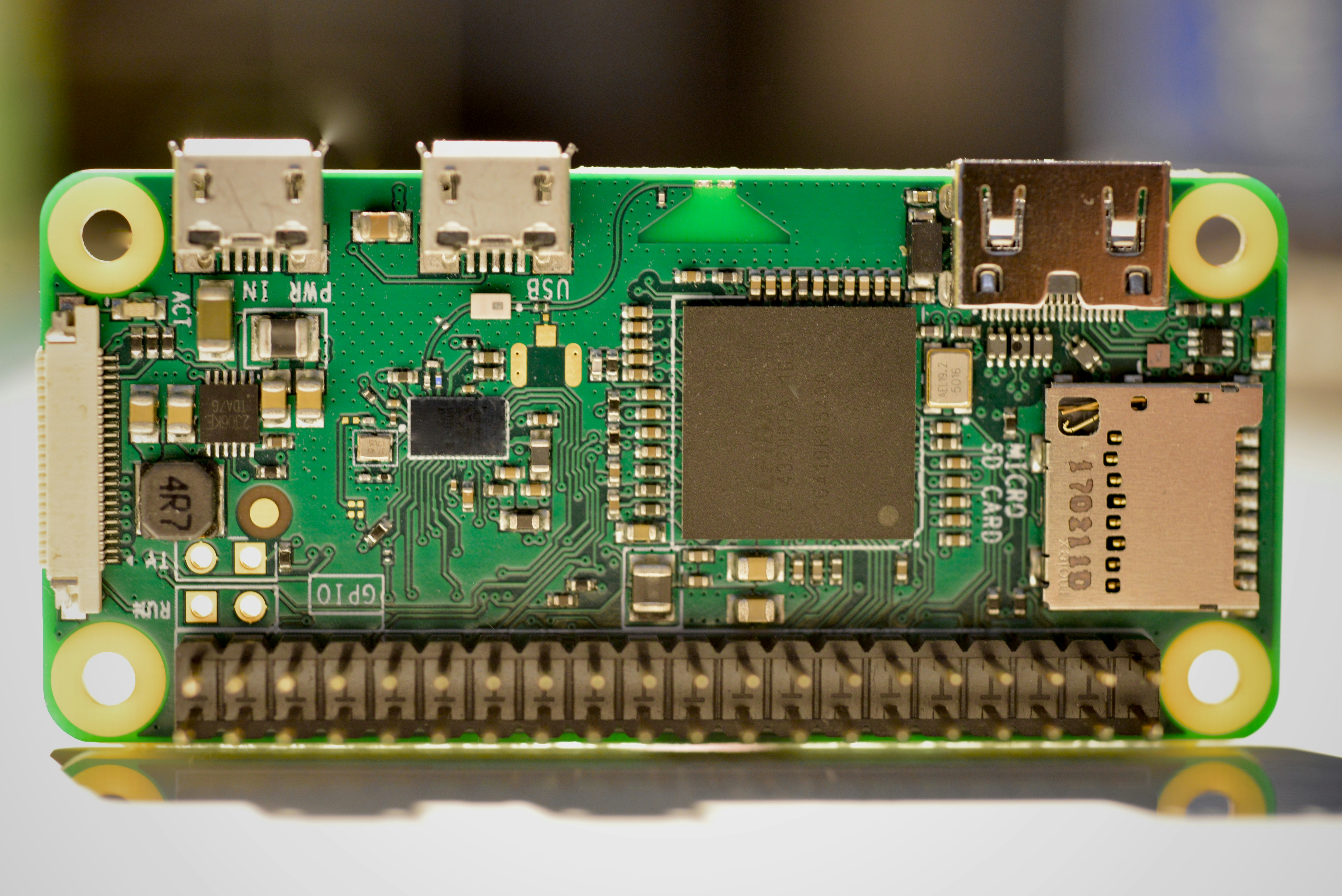
Template boards, also known as development boards, are pre-designed PCBs equipped with common microcontrollers or other integrated circuits (ICs), along with the necessary circuitry to support programming and prototyping. Examples include:
These boards offer a standardized platform for building and testing projects, facilitating rapid development, and experimentation.
PCBA
It is worth noting that a printed circuit board assembly (PCBA) is not the same as a PCB. While a PCB is not functional on its own, a PCBA includes the PCB itself and all the components soldered onto it, making it a complete and functional assembly for its intended application.
A PCBA (Image: Gavin Allanwood)
Differences between PCBs and breadboards
Materials and substrates
Breadboards
Breadboards are primarily made from a plastic body featuring numerous holes with metal strips underneath. These strips are usually made of spring metal to create a temporary electrical connection when the leads of components are inserted into the holes. Breadboards are inherently rigid due to their plastic construction, and are typically not used with flexible materials.
PCBs
Traditional PCBs are typically made from layers of fiberglass reinforced with epoxy resin, known as FR4. This material provides a sturdy, non-conductive substrate. The conductive paths are generally made of copper etched onto the board to form tracks that electrically connect components.
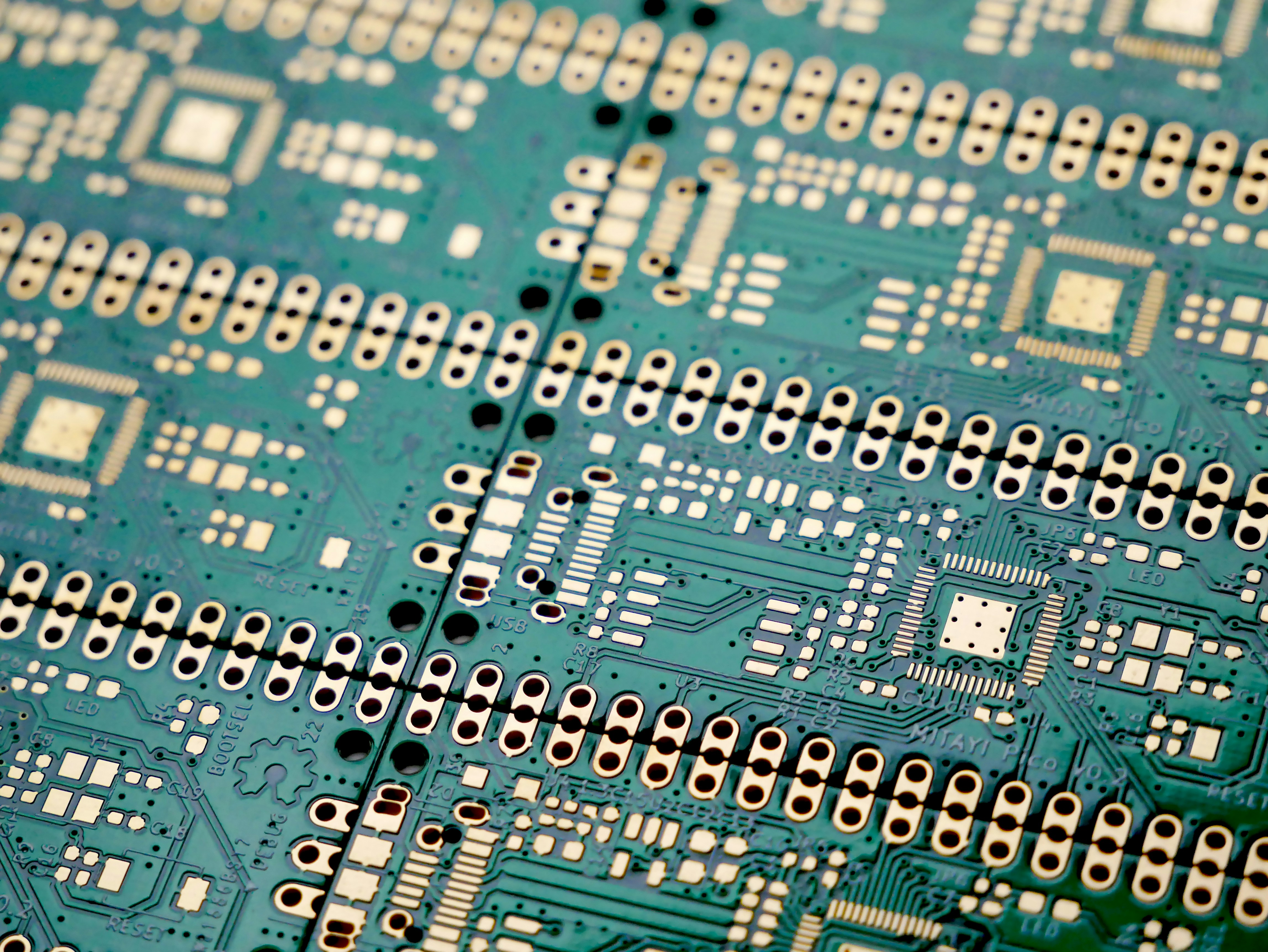
PCBs with Gold Finish (Image: Vishnu Mohanan)
Flexible PCBs
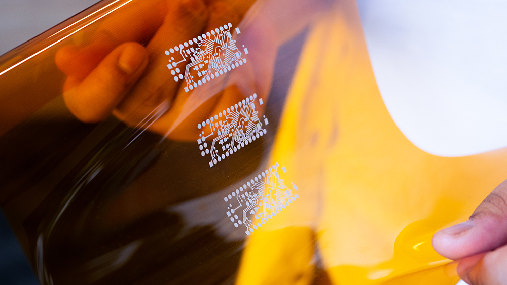
Flexible PCBs represent a variant of standard PCBs, made from materials that allow them to bend, flex, and move without breaking. Typically constructed from a flexible high-performance plastic like polyimide, these PCBs incorporate conductive copper layers and, in many cases, dielectric layers to ensure electrical insulation and mechanical strength.
Flexible pcbs printed by NOVA
Manufacturing processes and costs
Breadboards
Breadboards require no manufacturing for individual projects since they are reusable and do not need to be customized. This makes them cost-effective for initial testing and development. Prices generally range from a few dollars for basic models to higher amounts for larger or specialty types.
PCBs
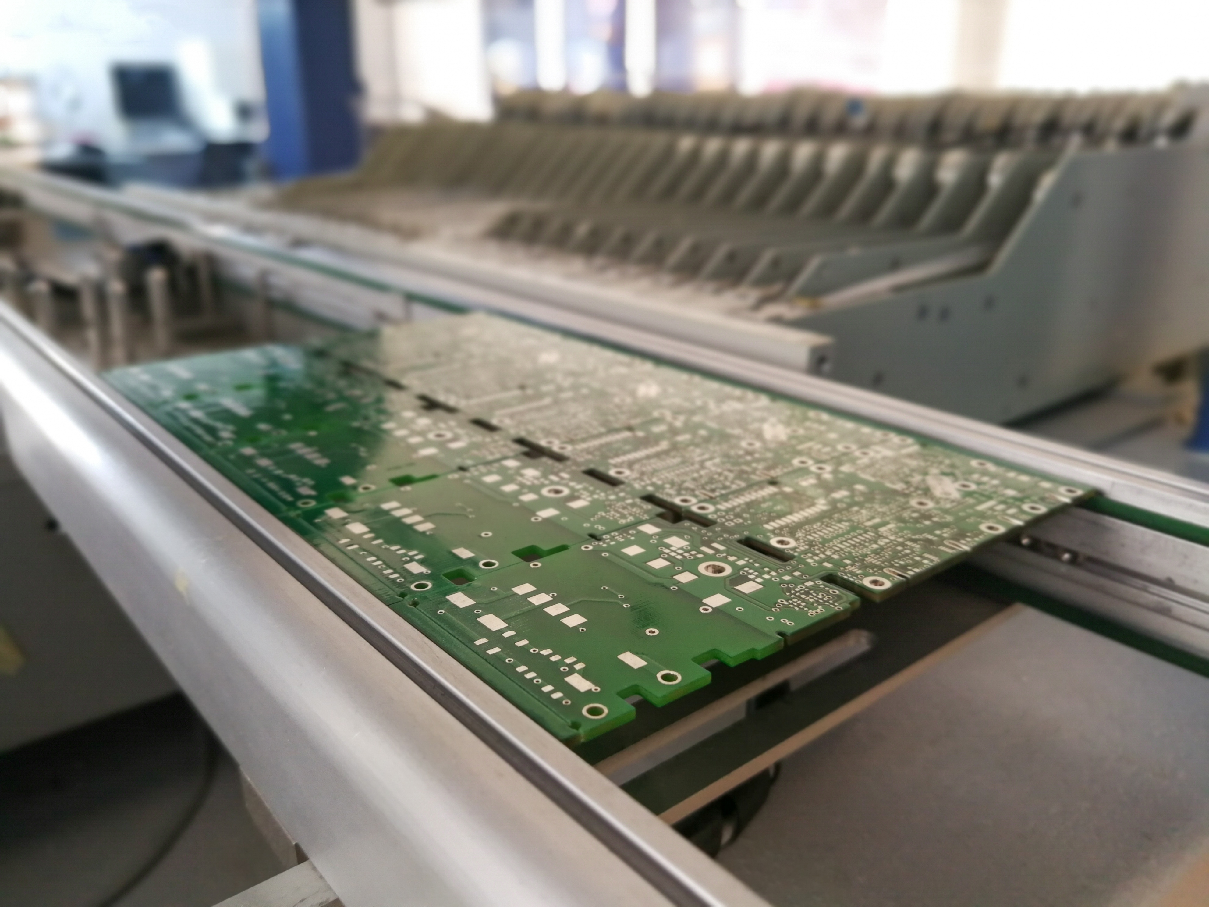
PCBs, on the other hand, involve a complex manufacturing process. This includes designing the circuit layout, printing the design onto the substrate, etching copper layers, drilling holes, and sometimes adding a protective solder mask and silk-screening component labels. The cost of producing PCBs can vary widely depending on the complexity of the design, the number of layers, and the quantity produced. While unit costs decrease with larger batch sizes, the initial setup and design work can be costly.
Traditional fabrication of PCBs (Image: Audrius Merfeldas)
The manufacturing of PCBs in a traditional factory setting is often not the most efficient approach, particularly when the process involves multiple iterations in quick succession. In such cases, the Voltera V-One PCB printer can be extremely useful. It allows users to modify their PCB designs on the fly and produce up to 15 boards in one day, while also ensuring that the design files and intellectual property remain secure.
Workflows
Breadboards
Breadboards are straightforward to use and require no special tools, making them ideal for beginners and those testing concepts or learning about circuits. Their non-permanent nature allows for easy adjustments and corrections without additional cost.
PCBs
PCBs, however, involve a significant upfront investment in design and planning. Designing a PCB typically requires using specialized software to lay out circuits, which can present a steep learning curve initially. However, for advanced projects and mass production, PCBs are more efficient once the initial setup is complete. They provide a more reliable and professional outcome, suitable for commercial products.
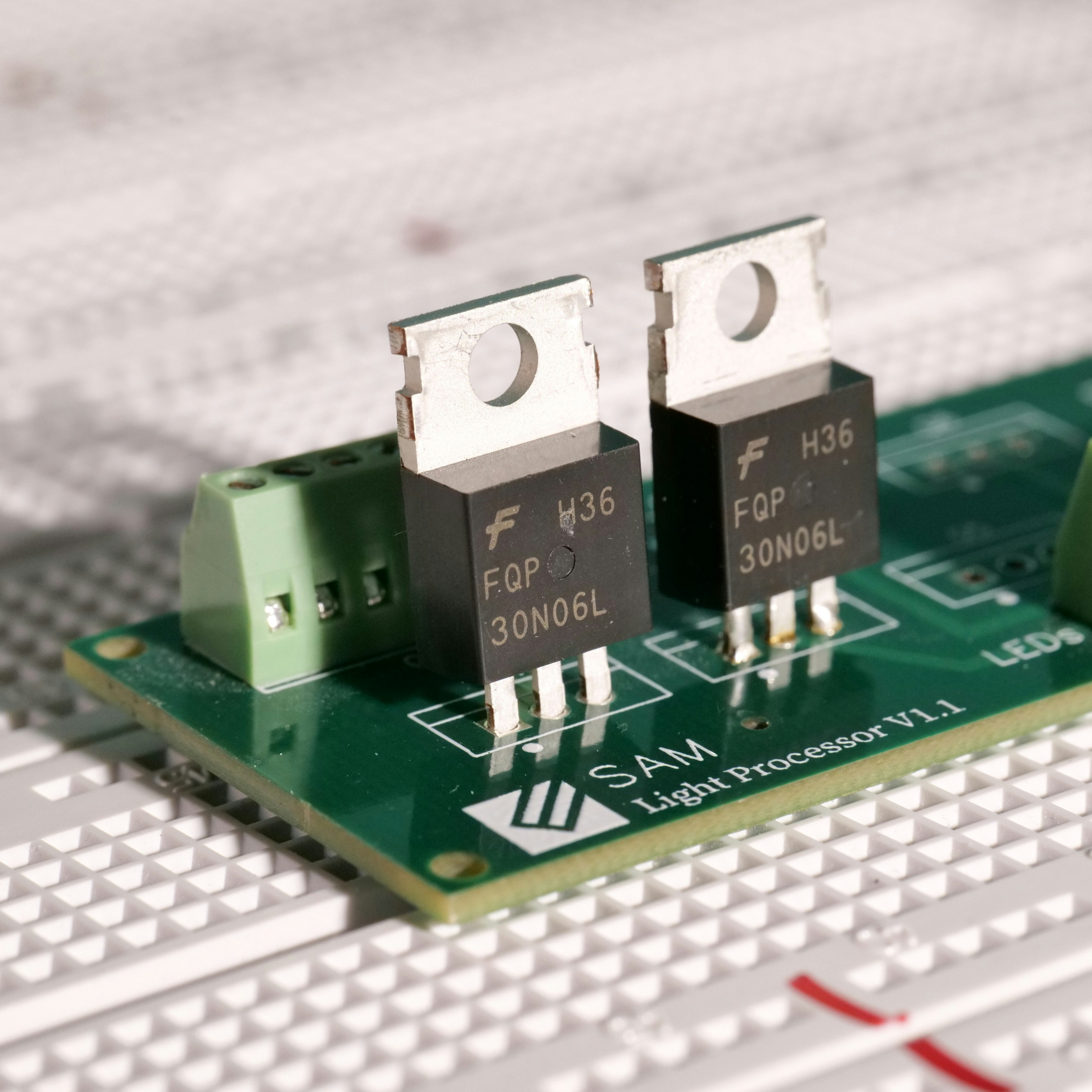
A PCB on breadboard (Image: Axel Richter)
Benefits and applications
Breadboards
Breadboards offer simplicity and flexibility, making them ideal for beginners and for educational purposes. They facilitate quick assembly and easy modifications of circuits without the need for soldering. This non-permanent setup is perfect for iterative testing and debugging, allowing users to learn and adjust as they go.
Breadboards are commonly used in educational settings to teach electronics, in hobbyist projects for experimenting with new circuit designs, and during the prototype testing phase of electronic development, especially when frequent adjustments are anticipated. Examples of projects using breadboards include FM radio transmitters, LED cubes, and digital thermometers.
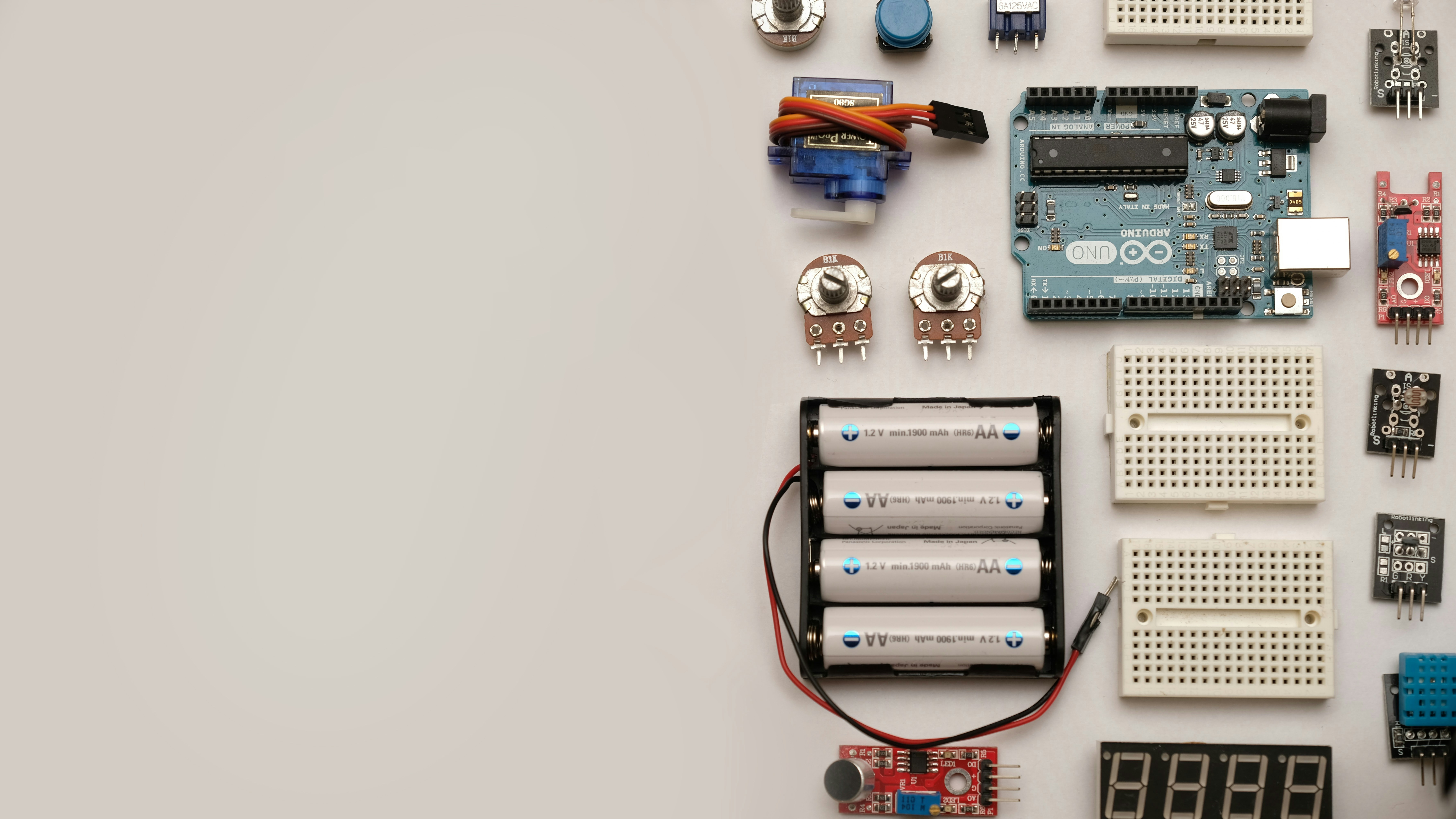
Breadboards and electronic components (Image: Robin Glauser)
PCBs
PCBs provide enhanced durability and reliability, supporting complex and multi-layered circuit designs with dense component placement, essential in professional-grade electronics. They are designed to handle more permanent and advanced applications, ensuring consistent performance over time.
PCBs are crucial in various industries, including consumer electronics, medical devices, automotive components, and other demanding applications that require long-term reliability and efficiency under varying environmental conditions. Examples of these applications include advanced driver-assistance systems, MRI scanners, and the flight control systems of drones.
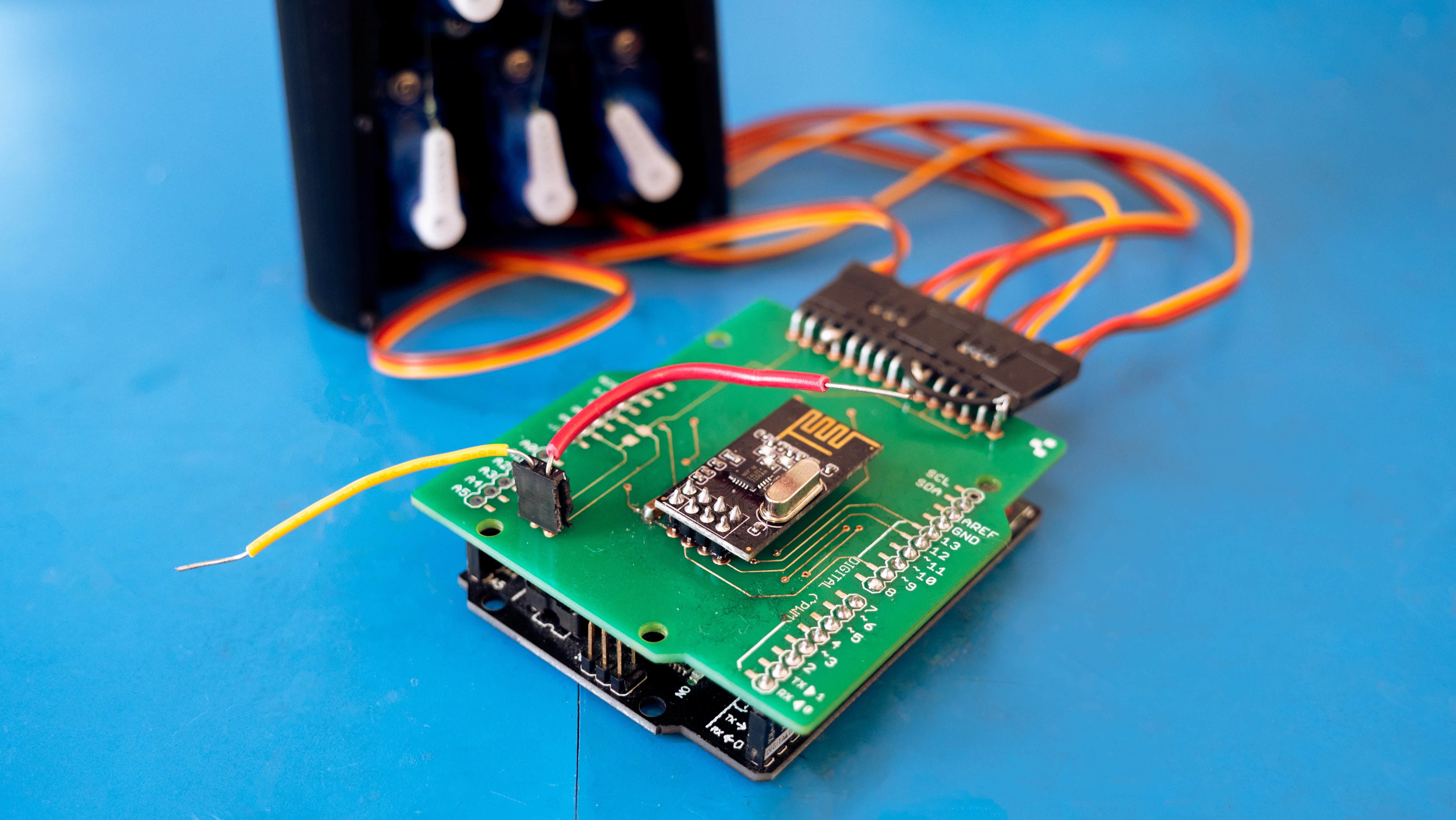
A PCBA for a remote control robotic hand made with V-One and NOVA
Conclusion
Both breadboards and PCBs play essential roles in electronics development. Breadboards are perfect for prototyping, testing, and educational purposes due to their flexibility and ease of use. On the other hand, PCBs are indispensable for final product development, offering stability, reliability, and suitability for complex and high-frequency circuits.
Understanding the strengths and limitations of each tool will help you choose the right one for your project, ensuring success in your electronics endeavors.
For more information on additively printed circuit boards, check out these projects:
- Printing a Magnesium Zinc Battery with Saral Inks on PET
- Printing Electroluminescent Ink on Paper and PET
- Printing a Flexible Membrane Keyboard with Conductive Silver Ink and Dielectric Ink on PET
- Printing Electronics with Carbon Ink
Meanwhile, if you have questions about your PCB printing needs, feel free to book a meeting with our specialists!

Explaining The CerAM Vat Photo Polymerization Based On JAMES Coin Design


